Signal jammer Electronics projects Circuit Diagram
BlogSignal jammer Electronics projects Circuit Diagram 4 Testing and Using the Signal Jammer. 4.1 Checking for Interference; The purpose of the circuit is to create a device that can block or disrupt the signals from cell phones, radios, and other communication devices. Here is a list of materials you will need to make a homemade signal jammer: Radio Frequency (RF)

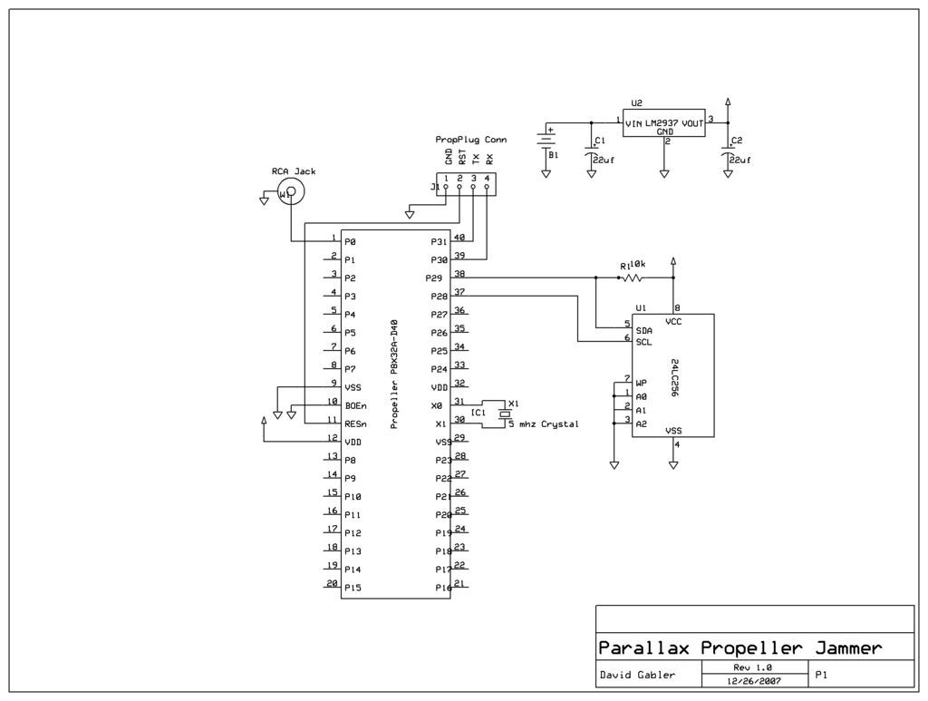
The document describes how to build a simple homemade RF signal jammer circuit that can jam RF signals within a 10 meter radius. It explains the circuit diagram and components, including two transistor oscillator and amplifier stages. It provides specifications for jamming different frequencies by adjusting inductors and trimmers. The document also discusses how to optimize the circuit by

How I made my signal jammer [Step by Step Guide] Circuit Diagram
2. DESIGN: The jammer design includes a capacitor, resistor, inductor, transistor, and NE555 timer IC to block the signal and amplify the generated signal from 800 MHz to 1.4 GHz, the same as a cell phone signal [14]. Fig 1- Design of Jammer 3.SIMULATION: Porteous software was used to simulate the jammer. All the
Source of Interference (usually built into the Tuning Circuit) RF Amplification Unit (the so-called "amplifier stage") Transmitting Antenna; The VCO is the most important part. It is like the heart of your jammer. The VCO produces an RF signal that will communicate with the device being blocked. First of all, you must select the frequencies
DIY Radio Frequency Jammer Guide Circuit Diagram
Building a mobile jammer requires a deep understanding of radio frequency (RF) engineering in Electronics. It involves complex circuit design, component selection, and testing. Essential components include oscillators, power amplifiers, antennas, and filters. Circuit design requires precise calculations. Circuit 1: Mobile Jammer Circuit using 555